Spiral path feed mode and oblique path feed mode
In the CNC milling machine processing, there are many technical problems to be considered, and the vertical feed mode setting is one of them. Using the Master CAM software for automatic programming, three vertical feed modes can be set: one is straight vertical downward feed; the other is spiral path feed mode; the third is oblique line path feed mode. These three vertical feed methods have their own advantages. They can be optimized to optimize the tool path and improve machining conditions, thus improving machining efficiency, workpiece machining accuracy and tool durability. Regarding the setting of the vertical feed mode, it involves a lot of parameters, and it is difficult to analyze it comprehensively. Here are a few ways to set up and optimize the vertical feed mode.
2 Comparison of three vertical feed modes 211 Direct vertical feed mode The direct vertical feed mode is a vertical downward feed, and the tool path is a straight line. In the automatic programming of MasterCAM software, most machining modes can only use direct vertical direction by default. Lower feed mode, such as "shape milling", "face milling", "surface finishing". These machining methods can be set by parameters, allowing the tool to feed vertically from the outside of the workpiece without cutting the material during the infeed. It can be seen that the direct vertical feed mode can only be used for keyway milling cutters with vertical knife-feeding capability when cutting material during the infeed process. Since the end portion of the end mill has no cutting edge, the cutting ability of the vertical feed is small, and the keyway cutter is a two-blade cutter whose end edge passes through the center of the milling cutter and has the ability to eat the knife vertically. However, since the keyway milling cutter has only two cutting edges, the machining is not smooth, the machining efficiency in the large-area cutting is low, and the surface roughness of the machined parts is not ideal. In actual machining, a drill is used to drill a hole in the solid part of the part before the multi-edge end mill is used for machining.
212 spiral path feed mode and oblique line path feed mode "2D groove machining" and "3D surface groove roughing" have spiral feed mode and oblique feed mode, which can be processed according to the processing. Choose one of the actual situations. These two machining methods feed directly from the top of the workpiece vertically downwards, cutting the material during the infeed. It can be seen that the spiral path feed mode and the oblique path path feed mode feed, the tool achieves the downward (Z-axis direction) feed, and the horizontal direction (X, Y direction) of the pass, is milling The side edge of the knife is gradually milled down to achieve a downward feed. Therefore, the spiral path feed mode and the oblique path feed mode can be used for the downward feed of the end mill with weak end cutting capability. However, the two feed modes have a longer trajectory, which reduces the processing efficiency. In actual machining, if the number of vertical feeds is large, the vertical feed mode is often adopted after drilling the process hole. If the number of vertical feeds is small, the spiral feed mode and the diagonal feed mode are often set. Especially in small batch production, in order to reduce the auxiliary time for clamping and tool setting, it is best to use a spiral or diagonal line feed.
3 spiral feed and slant feed setting steps When setting the tool path in MasterCAM software and programming CNC machining program, most machining methods can only use direct vertical downward feed mode, only in 2D machining "Scraping" and "grooving roughing" in 3D surface machining have the settings of the spiral feed mode and the oblique feed mode.
3112D "grooving processing" in the spiral feed and oblique line feed setting steps first use the CAD function of MasterCAM software to design the cavity contour, according to the following sequence operation can be carried out spiral feed mode and oblique line feed mode settings : Main function menu ??? Tool path ??? grooving ??? Select pocket contour ??? Execute ??? Execute ??? grooving dialog box. Then select the "rough milling / finishing parameters" item. On the right side of the dialog is a "spiral infeed or slash infeed" button with a square check box in front of the button. This button is normally in the dark display state. In this state, the tool feed mode is the vertical feed mode shown. If you use a spiral or diagonal feed method, then point
When the check box is pressed, the infeed mode button "spiral feed or oblique feed" is displayed in the clear state. At this time, click the button and the "spiral/slash parameter" setting dialog box appears. There are two options in the dialog: spiral feed and slash feed.
312 3D "grooving roughing" in the spiral feed and oblique line feed setting steps first use the Mas2 terCAM software CAD function to design the part model, according to the following sequence can be used for spiral feed mode and oblique line feed Mode setting: main function menu ??? tool path ??? surface processing ??? rough processing ??? trench roughing ??? select part model ??? execute ??? surface roughing grooving dialog box. Then select the "groove roughing parameters" item. There is a “spiral infeed or slash infeed†button above the middle of the dialog box with a square check box in front of the button. This button is normally in the dark display state. In this state, the tool feed mode is the vertical feed mode shown. If you want to use the spiral or oblique line feed method, click the check box, the feed mode button "spiral feed or oblique feed" is displayed in the clear state. At this time, click the button and the "spiral/slash parameter" appears. "Settings dialog. There are two options in the dialog: a spiral feed or a diagonal feed.
4 Typical application of vertical feed mode 411 Direct vertical feed process hole machining 41111 Method for determining the center position of the process hole When using the end mill direct vertical feed for "2D trenching" and "3D trench roughing", A drill bit must be used to drill a process hole in the body of the part. The determination of the center position of the process hole is the first problem to be solved before the process hole is processed, and it is also a difficult point in the process hole processing. A common approach is to determine the position of the center of the process hole by analyzing the NC machining program. If the workpiece shown in the machining is shown with the indicated path, the machining procedure for the post-travel processing is O1111. By analyzing the numerical control machining program O1111, the center position of the process hole is X - 121538Y - 61457 (see program O1111 4th) Row).
41112 Method for Determining the Depth of Process Holes “2D Grooving Machining†and “3D Trenching Machining†are directly fed perpendicularly with an end mill. A process hole should be drilled first. The depth control of the process hole is more accurate when machining the process hole. The depth of the process hole is too shallow, and it is very likely that the end mill will be damaged during the direct vertical feed process; if the depth of the process hole is too deep, it will cause the workpiece to be overcut and scrapped when it exceeds the position required for machining. How to determine the depth of the process hole, such as the workpiece shown, first use the "grooving roughing" to open the rough.
The depth of the hole drilled in the trench can be determined by analyzing the tool path in the front view. It can be seen that the drilling depth position is satisfactory between the "infeed end position" and the "drilling limit position" shown. Considering that the drill bit is conical, the process hole should be drilled under the “infeed end position†so that the end mill has sufficient direct vertical feed position. However, when machining the workpiece shown in a, the "infeed end position" and the "drilling limit position" are the same position. It is difficult to drill the process hole with the drill bit to meet the requirement of the vertical vertical feed of the end mill. In this case, a keyway cutter can be used. To process the process holes.
Application of the 412 "Infeed from outside the cutting range" option
The “Infeed from outside the cutting range†check box is often used for “drilling and roughing†of 3D surface machining, and “grooving roughing†often feeds from the top of the blank. For the workpiece shown, the “grooving roughing†should first be carried out to rough the blank and remove most of the material. When the two workpieces are thickened, one of the three feed modes: direct vertical downward feed, spiral path feed, and diagonal line feed can be used, but the direct vertical downward feed should first drill the process hole. . In the actual machining, when processing the workpiece shown only by removing the surrounding material, the “Infeed from outside the cutting range†check box can be selected to simplify the tool path and improve the machining efficiency.
413 "Droping along the boundary" application "Spiral / slash parameter" setting dialog box, there is a "Falling along the boundary into the knife" check box, select the "Falling along the boundary into the knife" check box, Set the tool to ramp down the edge. In actual machining, it is usually used to “fall in the edge along the boundary†when the spiral feed fails. However, after many times of processing, the author has flexibly applied the option of “falling into the knife along the boundaryâ€, and sometimes optimizes the infeed to obtain a relatively reasonable tool path.
Especially in the case where the machining workpiece cavity is small and the spiral feed radius is not too large. If the workpiece shown is machined, the infeed trajectory of "falling in the edge along the boundary" is as shown.
414 Spiral Infeed Spiral Radius Setting In the Spiral Infeed Parameter Setting dialog box, there are two parameters, “Minimum Radius†and “Maximum Radiusâ€, which are used to set the radius of the helix when the spiral feeds. The radius of the helix should be determined according to the size of the cavity and the depth of the milling. Generally, the larger the radius of the spiral, the longer the cutting distance of the infeed. When the "minimum radius" and "maximum radius" are set, the actual value of the helix radius is determined by the MasterCAM software based on the part model calculation. When the MasterCAM software calculates that the infeed at the maximum radius will interfere, the helix radius is the "maximum radius". When the computer enters the tool with the maximum radius, the system automatically adjusts the radius of the helix. The minimum radius of the helix is ​​the “minimum radiusâ€. When the MasterCAM software calculates that the tool is interfering with the minimum radius, the system sets the infeed mode to the direct vertical feed mode.
The actual radius of the helix when the spiral is fed is based on the final radius of the system. The programmer should pay attention to observe whether the actual radius of the spiral can meet the requirements of tool processing. The end portion of the end mill has no cutting edge, and the radius of the spiral when the spiral feed is at least should be greater than d /2.
Application of 415 oblique insertion type in the workpiece processing, when both the spiral feed and the oblique insert feed can meet the requirements, both the spiral feed and the oblique insert feed can be used. However, when machining long and narrow grooves as shown, the spiral radius of the spiral feed can not be too large, and it is preferable to use the oblique insert.
5 Conclusion
In this paper, three vertical feed modes in MasterCAM numerical control () machining are analyzed. The principle of feed mode and tool path setting is proposed for parts with different characteristics. The examples show that the analysis is correct and practical. Sex.
(Finish)Yellow Optical Brightener FP 127 (FBA 378)
Established in 2005, Forever Chemical Co., Ltd is a custom synthesis manufacturer, which headquartered in beautiful city Jinan, Shandong Province P.R. China. As an ISO 9001:2015 certificated company, Forever has a safety management system in place. It produces a wide range of chemicals to satisfy customers` needs. A greater percentage of optical brightener orders are now shipped the same day of receipt, especially yellow optical brightener OB-1, green optical brightener OB-1. Forever Chemical has established a global network of customers from many research centers, pharmaceutical companies and chemical factories.
Generally, in the production process of good water-based ink coatings, the fluorescent brightener OB is used. Fluorescent brightener OB not only increases the whiteness of the ink, but also increases the brightness of the ink. Fluorescent brightener OB-1 improves the grade of the product.
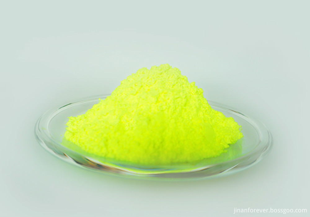
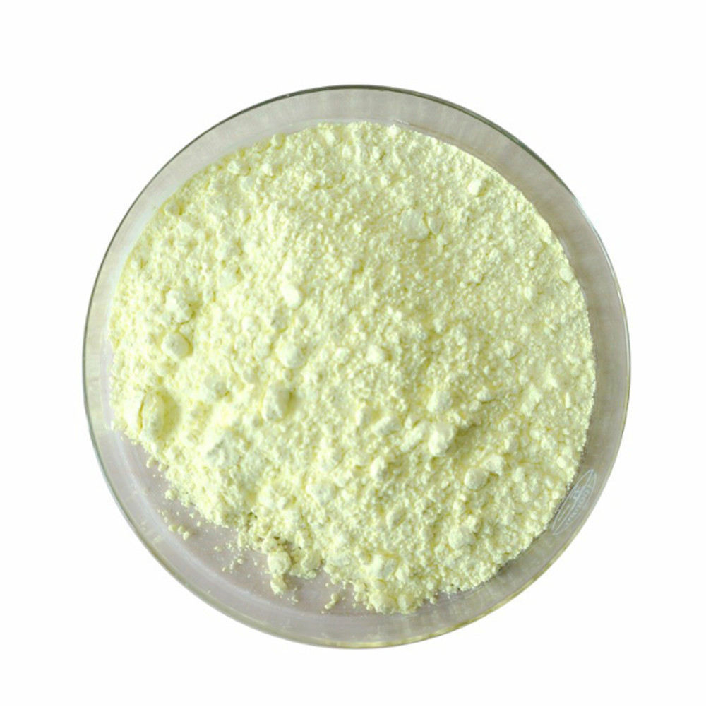
Forever Chemical has experienced experts, excellent manufacturing equipment, and a advanced R&D center. It owns the ability to provide optical brightener, yellow optical brightener OB-1, green optical brightener OB-1 from a few grams to kilograms, even to tons. And it also provides custom synthesis service, to help its customer with its best efforts. In Forever Chemical, we care about the quality and success of our customers` projects as if they were our own. We are committed into providing fluorescent brightener OB with reliable quality, competitive prices and superior service to our customers.
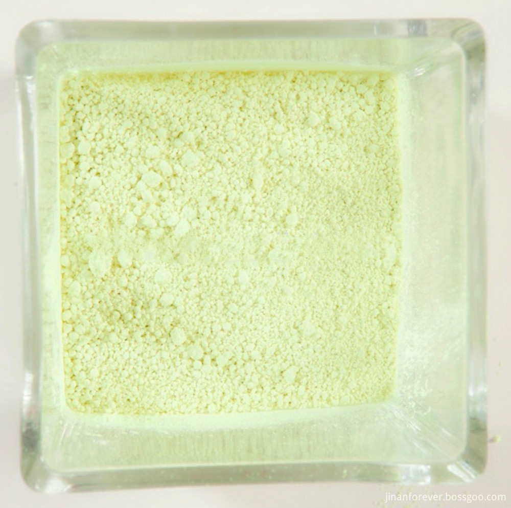

Yellow Optical Brightener OB-1,Optical Brightener For Plastic,Yellow Powder Optical Brightener Agent,Optical Brightening Agent OB-1
Jinan Forever Chemical Co., Ltd. , https://www.jinanforever.com