Design, field application and common faults of vortex flowmeter and their treatment methods
Design of vortex flowmeter and its field application and common faults in the field and its treatment method
1, vortex flowmeter and its advantages
China's vortex flowmeter production has developed rapidly. There are dozens of production plants in the country, but neither the theoretical research nor the practical experience of vortex flowmeters is insufficient. The basic flow equations so far still often refer to the Karman vortex theory, and this theory and some quantitative relationships are experimentally obtained by Kaman in a gas wind tunnel (uniform flow field), which has a three-dimensional uneven flow in a closed pipeline. The laws of vortex separation in the field are not the same. At present, vortex flowmeters are widely used in complex industrial sites such as oil pipelines, natural gas pipelines, smelters, and water pipelines.
In 1878, Strouhal published a paper on the relationship between fluid vibration frequency and flow velocity. The Strouhal number is a similarity criterion for the relationship between the vortex frequency and the size and velocity of the bluff body. Early research on vortex street was mainly used for disaster prevention, such as preventing damage to the equipment caused by the resonance between the natural frequency of the boiler and the heat exchanger tube and the fluid vortex frequency. The study of vortex fluid vibration phenomena used in measurements began in the 1950s, such as anemometers and ship speedometers. In the late 1960s, the development of closed-line pipe flowmeters - vortex flowmeters, was born with the hot wire detection method and the thermal detection method vortex flowmeter. In the 1970s and 1980s, the development of vortex flowmeters was extremely rapid, and many types of vortex flowmeters for bluffing and detection methods were developed and put into mass production.
   The vortex flowmeter is to place a non-streamline type bluff in the fluid. The fluid alternately separates and releases two regular vortices on both sides of the bluff body. In a certain flow range, the vortex separation frequency is proportional to the average flow velocity in the pipeline. By measuring the vortex frequency using various types of detecting elements, the flow rate of the fluid can be derived. Under certain flow conditions, a part of the fluid kinetic energy is converted into fluid vibration, and its vibration frequency has a certain proportional relationship with the flow rate (flow rate) . The flow meter operating according to this principle is called a fluid vibration flow meter . At present, there are three types of fluid vibration flowmeters : vortex flowmeters , precession (vortex precession) flowmeters and jet flowmeters . Vortex flowmeters have the following advantages [1].
1 The output is a pulse frequency whose frequency is proportional to the actual volume flow of the fluid being measured, and is not affected by fluid composition, density, pressure and temperature;
2 The measuring range is wide, generally up to 10:1 or more;
3 The accuracy is the upper middle level;
4 no moving parts, high reliability;
5 The structure is simple and firm, the installation is convenient, and the maintenance cost is low;
6 Wide range of applications for liquids, gases and vapours.
2, the working principle of vortex flowmeter
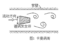
A vortex generator (blocking fluid) is disposed in the fluid, and a regular vortex is alternately generated from both sides of the vortex generator. This vortex is called a Karman vortex street (see Fig. 1), and the vortex column is asymmetric in the downstream of the vortex generator. Arranged in order. According to the principle of Karman vortex street, there is the following relationship [2]:
  

The ratio of the arcuate area on both sides of the m-vortex generator to the cross-sectional area of ​​the pipe; D-body diameter, mm; the width of the d-vortex body, mm; the frequency of f-vortex, Hz; U1-vortex Average flow velocity on both sides of the generator, m/s; Sr-Strouhal number; U-average fluidity of the measured medium, m/s.
The volumetric flow rate qv in the pipeline is:
  

In the formula, the meter coefficient of the K-flowmeter, the number of pulses / m3 is: P / m3.
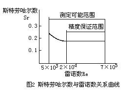
In addition to the geometry of the vortex generator and the pipe, it is also related to the Strouhal number. The Strouhal number is a dimensionless parameter, which is related to the shape of the vortex generator and the Reynolds number. Figure 2 shows the relationship between the Strouhal number of the cylindrical vortex generator and the Reynolds number of the pipe. It can be seen from Fig. 2 that in the range of ReD=2×10⁴~7×10⁶, the Strauhal number can be regarded as a constant, which is the normal working range of the instrument. When measuring the gas flow rate, the flow calculation formula of the vortex flowmeter is:
  

Where qvn,qv- are the volumetric flow under standard conditions (0°C or 20°C, 101.325kPa) and working conditions, m3/h; pn, p- are the pressure under standard conditions and working conditions, respectively, Pa Tn, T- are the thermodynamic temperatures under standard conditions and working conditions, respectively; K; Zn, Z- are the gas compression coefficients under standard conditions and working conditions, respectively.
It can be seen from equation (5) that the pulse frequency signal output by the vortex flowmeter is not affected by fluid physical properties and composition changes, that is, the meter factor is only related to the shape and size of the vortex generator and the pipeline within a certain Reynolds number range. However, as a flow meter, the mass flow rate needs to be detected in the material balance and energy metering. At this time, the output signal of the flow meter should simultaneously monitor the volume flow rate and the fluid density, and the fluid properties and components have a direct influence on the flow rate.
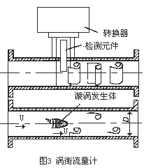
The vortex flowmeter consists of two parts, the sensor and the converter (see Figure 3). The sensor includes a vortex generator (blocking fluid), a detecting element, and an instrument body; the converter includes a preamplifier, a filter shaping circuit, a D/A conversion circuit, an output interface circuit, a terminal, a bracket, and a shield. In recent years, smart flow meters have placed microprocessors, display communications, and other functional modules in the converter.
The vortex generator is the main component of the detector. It is closely related to the flow characteristics (meter factor, linearity, range, etc.) and resistance characteristics of the meter. The requirements are as follows.
1 capable of controlling the synchronous separation of the vortex in the direction of the vortex generating body axis;
2 In the wider Reynolds number range, there is a stable vortex separation point, maintaining a constant Strouhal number;
3 can produce strong vortex, the signal has a high signal to noise ratio;
4 Simple shape and structure, easy to process and standardize geometric parameters and installation and combination of various detection components;
5 The material should meet the requirements of fluid properties, corrosion resistance, abrasion resistance and temperature resistance;
6 The natural frequency is outside the band of the vortex signal.
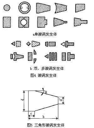
At present, many types of vortex generators have been developed at home and abroad, which can be divided into single vortex generators and multi-vortex generators (see Figure 4). The basic shape of the single vortex generator is a cylinder, a rectangular column, and a triangular column, and other shapes are deformations of these basic shapes. Among them, the triangular vortex generator is widely used (see Figure 5) [3]. In order to improve the strength and stability of the vortex, multi-vortex generators can be used, but their application is not universal.
  Â

3. Application of vortex flowmeter in the field
3.1 Field application
Vortex flowmeters are suitable for a wide range of fluids, but are not suitable for measuring low Reynolds number (ReD ≤ 2 × 10⁴) fluids. At low Reynolds numbers, the Strouhal number varies with the Reynolds number, the linearity of the instrument deteriorates, and the viscosity of the fluid is high, which significantly affects or even hinders the generation of vortices, and at the same time requires the fluid properties of the fluid. The fluid containing solid particles can cause noise to the vortex generator and cause wear to the vortex generator. If the short fibers contained are wound around the vortex generator, the meter factor will be changed. The application of vortex flowmeters in mixed-phase fluids is as follows:
1 It can be used for gas and liquid two-phase flow with dispersed and uniform micro-bubbles, but the volumetric gas content should be less than 7%~10%. If the volumetric gas content exceeds 2%, the meter factor should be corrected.
2 It can be used for gas-solid and liquid-solid two-phase flow containing dispersed and uniform solid particles with a content of not more than 2%.
3 It can be used for two-component flow of liquid and liquid (such as oil and water) which are insoluble in each other.
The pulsating and swirling flow will have a severe impact on the vortex flowmeter. If the pulsation frequency coincides with the vortex frequency, it may cause resonance, destroy normal operation and equipment, and cause the vortex signal to "lock-in", when the signal is fixed at a certain frequency. "Locking" is related to the pulsation amplitude, the shape of the vortex generator, and the clogging ratio.
The accuracy of the vortex flowmeter is approximately ±0.5% to ±2% for liquids and 0.2% to 0.5% for gas (1% to ±2%) R. Due to the low meter factor of the vortex flowmeter, the low frequency resolution, the larger the aperture, the lower the accuracy, so the gauge should not be too large (below DN300 [4]).
The range width is the advantage of the vortex flowmeter, and the flow rate value at the lower limit of the range is more important. Generally, the average liquid flow rate lower limit is 0.5m/s, and the gas is 4~5m/s [5]. The normal flow rate of the vortex flowmeter is 1/2~2/3 of the normal measurement range.
The advantage of the vortex flowmeter is that the meter factor is not affected by the physical properties of the measured medium. It can be verified by a typical medium and applied to other media, which is convenient for solving the calibration equipment problem. However, due to the wide range of flow rates of liquid and gas, the frequency range is also very different. In the amplifier circuit that processes the vortex signal, the passband of the filter is different and the circuit parameters are different. Therefore, the same circuit parameter cannot be used to measure different media. After the medium is changed, the circuit parameters should also change.
In addition, the density of gas and liquid varies widely, and the signal intensity produced by vortex separation is proportional to the density. Therefore, the signal intensity difference is also large, the gain and trigger sensitivity of the liquid and gas amplifier circuits are different, the piezoelectric charge difference is large, and the parameters of the charge amplifier are also different. Even if it is the same gas (or liquid, steam, etc.), depending on the pressure, temperature or density of the medium, the flow range used is different, the signal strength is different, and the circuit parameters are also changed. Therefore, a vortex flowmeter is not modified by hardware or software, and it is not feasible to change the use of media or instrument caliber.
Vortex flowmeters are widely used in industrial fields such as water treatment and oil pipelines. For example, Beijing Dongfang Chemical Plant uses 22 LUGB-type vortex flowmeters and supporting KSJ-type flow totalizers in the public works system, including water treatment and water secondary circulation. The water treatment mainly provides desalinated water for the start-up boiler. Providing refined water for ethylene and ethylene oxide to provide softening and dehydration water for secondary circulation of water; secondary circulation of water mainly provides circulating cooling water for ethylene, ethylene oxide, start-up boilers and water stations. In this project, the vortex flowmeter receives 12VDC power from the flow totalizer and uses a piezoelectric crystal element to detect the vortex separation frequency. The probe body installed inside the cylinder senses the pressure pulse generated by the vortex on both sides of the rear portion of the cylinder, and the piezoelectric crystal element embedded in the probe body senses the strain force, generates alternating charge, and is processed by the sensor. , output a pulse signal of a certain amplitude to the secondary instrument. The pulse signal is proportional to the flow through the pipeline. The proportional relationship is determined by the meter factor of the vortex flowmeter. The meter factor is generally calibrated by the manufacturer.
The flow totalizer is a flow display instrument based on the MCS51 series single-chip microcomputer 8031. After receiving this pulse signal, on the one hand, the pointer current meter displays the instantaneous flow rate, and the 8-bit digital display shows the accumulated flow or accumulated time, and the other It can output 4~20mA or 0~10mA signals for regulators or recorders. The flow totalizer performs parameter setting according to the meter coefficient and the flow range of the vortex flowmeter.
3.2 Installation Precautions
The vortex flowmeter is a flowmeter sensitive to the distortion of the flow velocity of the pipeline, the swirling flow and the flow of the artery. Therefore, the installation conditions of the on-site pipeline should be fully emphasized, and the instructions for use should be strictly followed.
Vortex flowmeters can be installed indoors or outdoors. If installed in a well, in order to prevent flooding, a hydrophobic sensor should be used. The sensor can be installed horizontally, vertically or obliquely on the pipe, but when measuring liquids and gases, in order to prevent interference from air bubbles and droplets, the installation position should be noted (see Figure 6).
The vortex flowmeter must ensure that the upper and downstream straight sections have the necessary length (see Figure 7).
The connection between the sensor and the pipe is shown in Figure 8. Pay attention to the following issues when connecting to pipes.
The inner diameter D of the upper and lower pipes is the same as the inner diameter D' of the sensor, and the difference satisfies the following condition: 0.95D ≤ D' ≤ 1.1D.
2 The piping should be concentric with the sensor, and the coaxiality is less than 0.05D'.
3 The gasket can not be protruded into the pipe, and its inner diameter can be 1~2mm larger than the inner diameter of the sensor.
4 If the flow check or cleaning sensor is required, a bypass pipe should be provided (see Figure 9) [6].


5 The impact of reducing vibration on the vortex flowmeter during field installation is worthy of attention. The vibration source should be avoided as much as possible, and the elastic hose should be connected in a small diameter and the pipe support should be added. A pipe support method is shown in Figure 10 [7].

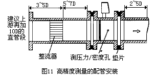
The complete installation includes front and rear straight pipe sections, and the flow regulator is a measure to ensure high-accuracy measurements. Assembly at the manufacturing plant ensures better installation quality. Figure 11 is an example of installation.
Electrical installation should be noted that a shielded cable or a low-noise cable should be used between the sensor and the converter, and the distance should not exceed the specifications in the instruction manual. Keep away from strong power cables when wiring, and try to protect them with separate metal sleeves. The "one-point grounding" principle should be followed and the grounding resistance is less than 10Ω. Both the integral and the split type should be grounded on the sensor side, and the ground point of the converter case should be “same ground†as the sensor.
3.3 Common faults, causes and troubleshooting methods on site
There are many ways to detect vortex flowmeters. The difference between sensors and measurement circuits is also large, but the common faults of vortex flowmeters have commonalities (see Table 1).
Table 1 vortex flowmeter failure and its treatment method
Fault phenomenon
possible reason
Approach
Output signal when there is no flow after power-on
1 input shielding or poor grounding, introduction of electromagnetic interference 2 instrument close to high-voltage equipment or high-frequency pulse interference source 3 pipeline has strong vibration 4 converter sensitivity is too high
1 Improve shielding and grounding, eliminate electromagnetic interference 2 Install away from interference sources, use isolation measures to enhance electromagnetic filtering 3 Take shock absorption measures, strengthen signal filtering, reduce amplifier sensitivity 4 Reduce sensitivity, increase trigger level
No output signal after power-on
1 power supply failure 2 input signal line disconnection 3 amplifier has a fault level 4 detection component damage
5 No flow or flow is too small 6 pipe blockage or sensor is stuck
1 Detect power supply and contact 2 Check signal line and terminal 3 to detect the working point, check component 4 to check sensor and lead, check valve, increase flow or reduce pipe diameter
5 check the cleaning pipe, clean the sensor
Output signal is not stable
1 Strong electrical interference signal 2 Sensor is contaminated or damaged, sensitivity is reduced 3 Sensor sensitivity is too high 4 Sensor is damaged or lead contact is poor
5 two-phase flow or pulsating flow 6 pipe vibration impact 7 process uncertainty 8 sensor installation different core or gasket protruding into the pipe 9 upstream and downstream valve disturbance 10 liquid not filled pipe
1 Strengthen shielding and contact 2 Clean or replace sensor, increase amplifier gain 3 Reduce gain, increase trigger level 4 Check sensor and lead
5 Strengthen the process, eliminate the two-phase flow or pulsating flow phenomenon. 6 Take the shock absorption measures. 7 Adjust the installation position. 8 Check the installation situation, correct the inner diameter of the gasket. 9 Lengthen the straight pipe section or install the flow regulator. Replace the location and method of installing the flow sensor.
Large measurement signal error
1 Straight pipe length is less than 2 Analog conversion circuit Zero drift or full scale adjustment is not correct 3 Power supply voltage changes too large 4 Meter exceeds verification period
5 The difference between the inner diameter of the sensor and the pipe is large. 6 Install the different center or the seal protrudes into the tube. 7 Sensor contamination or damage. 8 There are two-phase flow or pulsating flow. 9 Pipe leakage.
1 lengthen straight pipe section or install flow regulator 2 to correct zero point and range scale 3 check power supply 4 timely inspection
5 Check the inner diameter of the pipe, correct the meter factor 6 to adjust the installation, trim the gasket 7 and clean the replacement sensor 8 to eliminate the two-phase flow or the pulsating flow 9 to eliminate the leakage
Measuring tube leak
1 tube pressure is too high 2 nominal pressure selection is not correct for 3 seals 4 sensor is corroded
1Adjust the pipe pressure, change the installation position 2 Select the high-grade nominal pressure sensor 3 Replace the seal 4 to prevent corrosion and protect the night flow pressure
The sensor makes an unusual howling
1 The flow rate is too high, causing strong vibration 2. Producing cavitation 3
1Adjust the flow rate or replace the meter with large diameter. 2Adjust the flow rate and increase the flow pressure. 3 Tightening body
4 Conclusion
In the 1980s, China developed the vortex flowmeter standard (ZBN 12008-1989) and testing procedures (JJG 620-1989). Among many flowmeters, the purchase cost of vortex flowmeter is lower than that of mass and electromagnetic. Type, volumetric, etc., installation, operation, maintenance costs are lower than throttling, volumetric, turbine, etc., is a economical, more practical flowmeter. The vortex flowmeter has a simple and firm structure, convenient installation and maintenance, and is especially suitable for use in industrial sites such as smelters, chemical plants, and oil pipelines.
The disc dryer is a multi-layer fixed hollow heating circular carrier plate, rotating rake stirring, vertical continuous Drying equipment based on heat conduction. This kind of drying process is to pass the heating medium into the hollow discs of each layer, and indirectly heat the wet material placed on the disc surface by means of heat conduction. Under the action of the scraper of the rotating blades, the material is continuously moved and rolled. The water evaporates at the operating temperature, and its steam is discharged with the exhaust gas of the equipment, so as to continuously obtain qualified dry products at the bottom of the equipment.
Disc Dryer,Rotary Disc Dryer,Vacuum Disc Dryer,Compact Disc Dryer
Griffin Technology Manufacturing Co., Ltd. , https://www.griffindryingeqpt.com