Analysis and Research on Application of Fieldbus Technology in Thermal Power Plant Control
Abstract: Fieldbus has a wide range of applications. Everyone is familiar with it. The most classic is the application in thermal power plants. This article describes the generation and development of fieldbuses and the design of fieldbus control in thermal power plants. Through discussion, this new technology has been well applied in the electric power industry as soon as possible, and the automation level of thermal power plants has reached a new level.
1. Introduction to Fieldbus In the development of automatic control technology of thermal power plants, only from the perspective of the development of digital control systems, the evolution process from DDC to DCS to FCS is shown in Figure 1.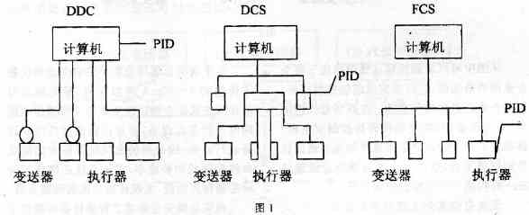
From the figure, it can be seen that its intelligent computing gradually shifts from a centralized computer to a relatively decentralized controller; finally, it transfers to local control equipment. In the early days of fieldbus technology, its main function was to connect the PLC at the time in a more concise manner. With the development of computer communication technology, the function of fieldbus has been greatly enhanced, which has become the main trend of fieldbus technology development.
Fieldbus technology is defined as: The special microprocessor is embedded in the traditional measurement and control instruments, so that they have digital computing and communication capabilities, using twisted pair as the bus, a number of control instruments, connected to the network system, press The open and standard communication protocol realizes data transmission and information exchange between devices with multiple measurement and control calculation functions at the site, as well as between field instruments and monitoring computers, and forms a fully distributed automatic control system at the production site. Providing richer information that enables people to better understand the state of process automation equipment management information has taken a big step toward intelligent, digital, information, networking, and decentralized automation systems.
This definition is not necessarily accurate, but it covers the connotation and implications of the fieldbus. It is also possible to describe the field bus as a communication system and control system that uses a “phone line†to connect transmitters, field switches, actuators, etc., and further interconnect it with monitoring, management, business, and other hierarchical networks. One, as shown in Figure 2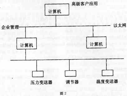
From the figure, we can see that the fieldbus network is located at the bottom of the entire enterprise network. It is responsible for completing the on-site control tasks and is also the basis for enterprise information integration. In a fieldbus network, each device (including the field instrumentation and the control room host) is equivalent to a network node that can independently assume certain control and communication tasks. These nodes are connected together via fieldbus to form a complete control system.
Fieldbus is actually the "Internet" in automatic control systems. It uses digital communication technology to make the automatic control system organically added to the thermal power plant information network to form a factory floor network, so that the scope of power plant information communication can be extended down to the production site. The field device perfectly combines the field device and the control system through a certain standard communication protocol, just as a public digital language is completed for the field device and the control system as long as the field device and the control system can understand and Using this language, they can communicate well with each other to achieve interoperability between devices.
Since fieldbus replaced all traditional 4-20mA analog signals with all-digital bi-directional communication, the original point-to-point wiring method can now be changed to connect multiple devices at the same time using a single communication cable, and the device can also be powered through the bus. The fieldbus can greatly simplify the wiring and reduce the initial installation cost. The fieldbus also strengthens the control of the field segment and realizes the complete dispersion of control functions.
Fieldbus fully integrates the on-the-spot information provided by smart devices, such as device fault diagnosis and configuration information. System maintenance personnel can accurately and quickly understand the operating status of the production site and equipment, and can be quickly eliminated once a fault occurs. Can discover the potential breakdown, eliminate the hidden danger ahead of time, and DCS can't carry on the fault diagnosis to the on-the-spot equipment, this is also FCS better than DCS.
2. Fieldbus control system design Fieldbus control system and conventional control system and DCS system have many similarities in the system configuration function, control strategy and other aspects, such as a simple single network control system whose basic constituent elements are measurement transmission. Unit, operation execution unit shown in Figure 3
 The most important feature of the fieldbus system is that its control unit can be integrated with the measurement transmission unit and the operation execution unit in the physical location, so that it can communicate and synthesize information in the on-site intelligent equipment, which facilitates the complex control in which multiple variables are involved. System and precision measurement system. In addition, because of the digital communication characteristic of the fieldbus instrument, it not only can transmit the measured numerical information but also can pass the information such as equipment identification, running status, fault diagnosis status, etc., thus can form the apparatus resource management system of the intelligent instrument.
Taking the boiler drum water level of thermal power plant as an example, the characteristics of field bus control system in design, installation and operation are introduced. As shown in Figure 4, the three-impulse control system for drum level is a classical control scheme that is often used.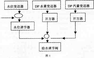
Once the plan is selected, you can start designing.
(1) Select necessary field smart meters according to the control plan
A classic three-impulse water level control system requires a level transmitter; two flow transmitters for steam flow, feed flow, and one feedwater control valve. Fieldbus control systems also need these transmitters and actuators. For the general analog instrumentation control system, since the drum water level, steam flow rate, feedwater flow rate, and the measurement signal itself fluctuate frequently, the damper is required to preprocess the measurement signal. According to the factory's conventional orifice plate plus differential pressure transmitter to measure the flow, in order to make the measurement signal and the flow rate linear, a squarer must be added; besides, two regulators such as the master and the slave of cascade control should be formed. In the field bus system, the functions of damping, square root, addition and subtraction PID calculation are completely realized by software embedded in the field transmitter and actuator. Can reduce hardware investment, save installation man-hours and cables.
(2) Selecting computers and network accessories In order to meet the requirements of configuration, operation and operation of on-site smart devices, it is generally necessary to select one or more computers that can be connected to the fieldbus network, with industrial PCs already in the field of control. With increasing popularity, many fieldbus control systems with different communication protocols use PC fieldbus interface boards inserted in PC bus slots to connect industrial PCs and fieldbus networks to complete functions such as configuration and operation. Control and network system The PC fieldbus interface board can have several fieldbus channels that can integrate several fieldbus segments. Power supplies, terminators, cables, etc., are the basic hardware of the fieldbus system as shown in Figure 5:
In the figure, five computers are mainly configured for security redundancy. The PCI interface card has four channels. Each PCI interface card is connected to four total network segments.
Another more suitable method is to design a communication controller whose one side is connected with a field bus network segment and the other side is connected with a commonly used PC networking method, such as through Ethernet, using a TCP/IP communication protocol, The network BIOS protocol completes the exchange of information between the fieldbus network segment and the PC.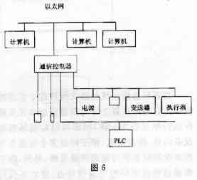
In order to optimize the communication and reduce the round-trip transmission of signals, the field devices related to the signals in the same control system are arranged as close as possible to the same bus segment. In addition to the above-mentioned water level, flow transmitters, feedwater control valves, etc., there are PLCs for interlocking system switching control in the boiler control system. It also needs to exchange information with field transmitters, etc. It can use PLC and fieldbus segment interfaces to make PLC a node member of the fieldbus network segment.
(3) Select man-machine interface software MMI to develop configuration software and control operators
Configuration software is a featured software in fieldbus systems. It is responsible for completing the following tasks.
a. Select the connected fieldbus device on the application software interface.
b. Allocate signals with the selected device.
c. Select the function block from the function library of the device.
d. Implement functional block links.
e. Feature parameters are assigned to function blocks as required by the application.
f. Download kit information for field devices.
(4) According to the control system structure and the required functional blocks of the control strategy and the conditions of the functional block library that the intelligent field device has, allocate the location of the functional block.
Specific to the three-impulse water level control system, the function block allocation scheme is as follows:
a. In the drum level transmitter, the AI ​​analog input function block and the main regulator PID function block are selected.
b. In the water flow transmitter, the AI ​​analog input function block and the summation algorithm function block are selected.
c. In the steam flow transmitter, use AI analog input function block.
d. In the positioner of the valve, the sub-regulator PID function block and AO output function block are selected, and the barometric pressure conversion from the field bus function block to the regulating valve is realized.
(5) Through the configuration software, complete the connection of the function block shown in Figure 7: distribution and connection of function blocks
According to the three-impulse control system diagram and the function block allocation scheme, the function block kits are connected, such as the position number LTl01 of the water level transmitter, the position numbers of the steam and the water supply transmitter are FTl02, FTl03, and the position of the water supply regulating valve. No. FVl01.
BK-CALin: Input of valve position feedback signal.
BK-CALout: output of valve position feedback signal CAS-IN: indicates that the cascade input (6) is characterized by a function block and the corresponding parameter is determined for each function block.
The configuration determines the characteristic parameters of its AI function block, such as the measurement input range, output range, engineering unit, filter time, whether to require open source processing, etc.
(7) Network configuration Since the fieldbus is the bottom layer network, the scope of the network configuration includes the fieldbus network segment, as well as the PC as the man-machine interface operation interface and the network segment connected to it.
(8) The last operation of the configuration is to download the configuration information, that is, send the code of the configuration information to the corresponding field device and start the system operation.
Through the above method, the fieldbus control system design is completed.
3, fieldbus control system software software consists of the following components:
(1) Configuration software (2) Maintenance software (3) Simulation software (4) Field equipment management software (5) Monitoring software 4, OPC introduction After designing the control system, I will mention OPC technology.
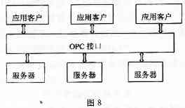
The abbreviation of OPC-OLEforProcessControl means object link embedding technology in process control. This is a technical specification and standard, and OPC serves as an effective communication tool between field devices and factory office applications in automated systems. Simple and standardized data exchange between office and production departments.
We know that integrating parts from different manufacturers is a nuisance. We need to develop drivers or service programs specifically for each part. You also need to link these driver or service programs provided by the manufacturer with the application. The role of OPC is to provide a uniform, standard interface specification for server/client links, and should ultimately be formed as shown in the figure:
 5. Concluding remarks Fieldbus technology is being gradually applied in power plants. For example, the Banshan Power Plant in Zhejiang Province has used part of the fieldbus technology to achieve success and hopes to be more widely used in thermal power plants.
Fieldbus devices such as the 3051 transmitter and Bernard's actuators that have been developed by various manufacturers already possess this type of functionality.
As the power plant welcomes more fieldbus-enabled devices to be applied to the site, it is of great benefit to reduce the failure rate of equipment and reduce the labor intensity of workers, especially for centralized control of auxiliary workshops, and to improve the automation level of thermal power plants.
1. Introduction to Fieldbus In the development of automatic control technology of thermal power plants, only from the perspective of the development of digital control systems, the evolution process from DDC to DCS to FCS is shown in Figure 1.
From the figure, it can be seen that its intelligent computing gradually shifts from a centralized computer to a relatively decentralized controller; finally, it transfers to local control equipment. In the early days of fieldbus technology, its main function was to connect the PLC at the time in a more concise manner. With the development of computer communication technology, the function of fieldbus has been greatly enhanced, which has become the main trend of fieldbus technology development.
Fieldbus technology is defined as: The special microprocessor is embedded in the traditional measurement and control instruments, so that they have digital computing and communication capabilities, using twisted pair as the bus, a number of control instruments, connected to the network system, press The open and standard communication protocol realizes data transmission and information exchange between devices with multiple measurement and control calculation functions at the site, as well as between field instruments and monitoring computers, and forms a fully distributed automatic control system at the production site. Providing richer information that enables people to better understand the state of process automation equipment management information has taken a big step toward intelligent, digital, information, networking, and decentralized automation systems.
This definition is not necessarily accurate, but it covers the connotation and implications of the fieldbus. It is also possible to describe the field bus as a communication system and control system that uses a “phone line†to connect transmitters, field switches, actuators, etc., and further interconnect it with monitoring, management, business, and other hierarchical networks. One, as shown in Figure 2
From the figure, we can see that the fieldbus network is located at the bottom of the entire enterprise network. It is responsible for completing the on-site control tasks and is also the basis for enterprise information integration. In a fieldbus network, each device (including the field instrumentation and the control room host) is equivalent to a network node that can independently assume certain control and communication tasks. These nodes are connected together via fieldbus to form a complete control system.
Fieldbus is actually the "Internet" in automatic control systems. It uses digital communication technology to make the automatic control system organically added to the thermal power plant information network to form a factory floor network, so that the scope of power plant information communication can be extended down to the production site. The field device perfectly combines the field device and the control system through a certain standard communication protocol, just as a public digital language is completed for the field device and the control system as long as the field device and the control system can understand and Using this language, they can communicate well with each other to achieve interoperability between devices.
Since fieldbus replaced all traditional 4-20mA analog signals with all-digital bi-directional communication, the original point-to-point wiring method can now be changed to connect multiple devices at the same time using a single communication cable, and the device can also be powered through the bus. The fieldbus can greatly simplify the wiring and reduce the initial installation cost. The fieldbus also strengthens the control of the field segment and realizes the complete dispersion of control functions.
Fieldbus fully integrates the on-the-spot information provided by smart devices, such as device fault diagnosis and configuration information. System maintenance personnel can accurately and quickly understand the operating status of the production site and equipment, and can be quickly eliminated once a fault occurs. Can discover the potential breakdown, eliminate the hidden danger ahead of time, and DCS can't carry on the fault diagnosis to the on-the-spot equipment, this is also FCS better than DCS.
2. Fieldbus control system design Fieldbus control system and conventional control system and DCS system have many similarities in the system configuration function, control strategy and other aspects, such as a simple single network control system whose basic constituent elements are measurement transmission. Unit, operation execution unit shown in Figure 3
Taking the boiler drum water level of thermal power plant as an example, the characteristics of field bus control system in design, installation and operation are introduced. As shown in Figure 4, the three-impulse control system for drum level is a classical control scheme that is often used.
Once the plan is selected, you can start designing.
(1) Select necessary field smart meters according to the control plan
A classic three-impulse water level control system requires a level transmitter; two flow transmitters for steam flow, feed flow, and one feedwater control valve. Fieldbus control systems also need these transmitters and actuators. For the general analog instrumentation control system, since the drum water level, steam flow rate, feedwater flow rate, and the measurement signal itself fluctuate frequently, the damper is required to preprocess the measurement signal. According to the factory's conventional orifice plate plus differential pressure transmitter to measure the flow, in order to make the measurement signal and the flow rate linear, a squarer must be added; besides, two regulators such as the master and the slave of cascade control should be formed. In the field bus system, the functions of damping, square root, addition and subtraction PID calculation are completely realized by software embedded in the field transmitter and actuator. Can reduce hardware investment, save installation man-hours and cables.
(2) Selecting computers and network accessories In order to meet the requirements of configuration, operation and operation of on-site smart devices, it is generally necessary to select one or more computers that can be connected to the fieldbus network, with industrial PCs already in the field of control. With increasing popularity, many fieldbus control systems with different communication protocols use PC fieldbus interface boards inserted in PC bus slots to connect industrial PCs and fieldbus networks to complete functions such as configuration and operation. Control and network system The PC fieldbus interface board can have several fieldbus channels that can integrate several fieldbus segments. Power supplies, terminators, cables, etc., are the basic hardware of the fieldbus system as shown in Figure 5:
In the figure, five computers are mainly configured for security redundancy. The PCI interface card has four channels. Each PCI interface card is connected to four total network segments.
Another more suitable method is to design a communication controller whose one side is connected with a field bus network segment and the other side is connected with a commonly used PC networking method, such as through Ethernet, using a TCP/IP communication protocol, The network BIOS protocol completes the exchange of information between the fieldbus network segment and the PC.
In order to optimize the communication and reduce the round-trip transmission of signals, the field devices related to the signals in the same control system are arranged as close as possible to the same bus segment. In addition to the above-mentioned water level, flow transmitters, feedwater control valves, etc., there are PLCs for interlocking system switching control in the boiler control system. It also needs to exchange information with field transmitters, etc. It can use PLC and fieldbus segment interfaces to make PLC a node member of the fieldbus network segment.
(3) Select man-machine interface software MMI to develop configuration software and control operators
Configuration software is a featured software in fieldbus systems. It is responsible for completing the following tasks.
a. Select the connected fieldbus device on the application software interface.
b. Allocate signals with the selected device.
c. Select the function block from the function library of the device.
d. Implement functional block links.
e. Feature parameters are assigned to function blocks as required by the application.
f. Download kit information for field devices.
(4) According to the control system structure and the required functional blocks of the control strategy and the conditions of the functional block library that the intelligent field device has, allocate the location of the functional block.
Specific to the three-impulse water level control system, the function block allocation scheme is as follows:
a. In the drum level transmitter, the AI ​​analog input function block and the main regulator PID function block are selected.
b. In the water flow transmitter, the AI ​​analog input function block and the summation algorithm function block are selected.
c. In the steam flow transmitter, use AI analog input function block.
d. In the positioner of the valve, the sub-regulator PID function block and AO output function block are selected, and the barometric pressure conversion from the field bus function block to the regulating valve is realized.
(5) Through the configuration software, complete the connection of the function block shown in Figure 7: distribution and connection of function blocks
According to the three-impulse control system diagram and the function block allocation scheme, the function block kits are connected, such as the position number LTl01 of the water level transmitter, the position numbers of the steam and the water supply transmitter are FTl02, FTl03, and the position of the water supply regulating valve. No. FVl01.
BK-CALin: Input of valve position feedback signal.
BK-CALout: output of valve position feedback signal CAS-IN: indicates that the cascade input (6) is characterized by a function block and the corresponding parameter is determined for each function block.
The configuration determines the characteristic parameters of its AI function block, such as the measurement input range, output range, engineering unit, filter time, whether to require open source processing, etc.
(7) Network configuration Since the fieldbus is the bottom layer network, the scope of the network configuration includes the fieldbus network segment, as well as the PC as the man-machine interface operation interface and the network segment connected to it.
(8) The last operation of the configuration is to download the configuration information, that is, send the code of the configuration information to the corresponding field device and start the system operation.
Through the above method, the fieldbus control system design is completed.
3, fieldbus control system software software consists of the following components:
(1) Configuration software (2) Maintenance software (3) Simulation software (4) Field equipment management software (5) Monitoring software 4, OPC introduction After designing the control system, I will mention OPC technology.
The abbreviation of OPC-OLEforProcessControl means object link embedding technology in process control. This is a technical specification and standard, and OPC serves as an effective communication tool between field devices and factory office applications in automated systems. Simple and standardized data exchange between office and production departments.
We know that integrating parts from different manufacturers is a nuisance. We need to develop drivers or service programs specifically for each part. You also need to link these driver or service programs provided by the manufacturer with the application. The role of OPC is to provide a uniform, standard interface specification for server/client links, and should ultimately be formed as shown in the figure:
Fieldbus devices such as the 3051 transmitter and Bernard's actuators that have been developed by various manufacturers already possess this type of functionality.
As the power plant welcomes more fieldbus-enabled devices to be applied to the site, it is of great benefit to reduce the failure rate of equipment and reduce the labor intensity of workers, especially for centralized control of auxiliary workshops, and to improve the automation level of thermal power plants.
special-purpose vehicel suitable for agitating and transiting concrete,
for construction site, road repairing and some other infrastructure construction business.
We design and produce as demand in use purpose for your project or special demand.
such as LED caro truck, Advertising vehicle, Refrigerated transporter,Livestock transporter,Log truck,animals carrier, cow truck, chicken transport truck , coca cola lorry truck etc...
Special-Purpose Vehicle,Special Vehicles,Special Dump Truck,Special Trucks
SINO VEHICLE AND EQUIPMENT COMPANY LTD , https://www.sinoauto-machinery.com