Design and Research of Advanced PID Function Block of FCS165 Fieldbus Control System
First, the APID algorithm FCS165 fieldbus control system sub-PID control algorithm, which includes the proportion of up (n) APID using the actual micro, integral ui (n), differential ud (n) and feedforward FF (n) 4 links, The function is: 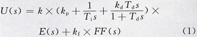
Where: U is the control quantity; k is the total gain; E is the deviation value of the process quantity VP and the set value SP after the gain and offset standardization processing; kp is the proportional gain; kd is the differential gain; kf is the former Feed-in gain; Td is the integration time constant; Td is the derivative time constant.
In order to facilitate the realization of the APID algorithm on the computer, the formula (1) should be discretized, and the expression obtained after discretization of up(n), ui(n), ud(n), and u(n) is:
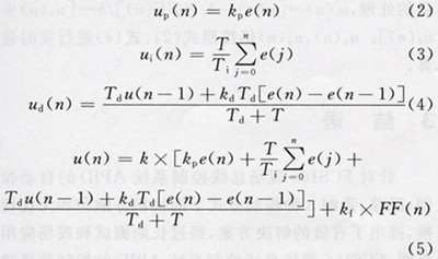 Where: T is the operation period; n is the operation number; e(n), e(n-1) are the deviation values ​​of the nth and (n-1)th operation periods, respectively; FF(n) is the nth. The feedforward value of each operation cycle; u(n), u(n-1) are the control quantities for the nth and (n-1)th operation cycles, respectively.
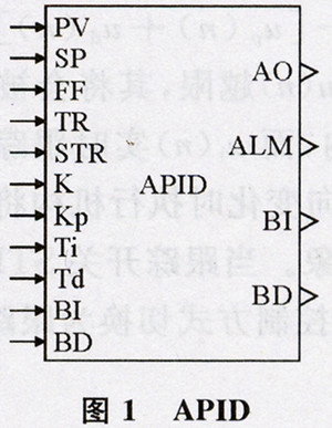
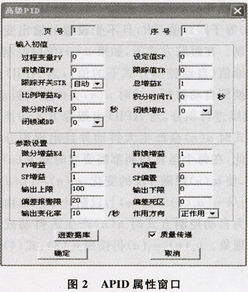
The APID and property windows are shown in Figures 1 and 2. APID has a total of n input pins, which can be connected to the output pin of the previous function block for PID operation. An adaptive control scheme is designed by connecting the APID input pin and the output pin of the upper functional block. If some parameters of the total gains k, kp, Ti, and Td do not require adaptive control, the corresponding parameters in the attribute window may be modified in real time by an on-line command according to the needs of the operating conditions. The operation parameters of the APID algorithm take the attribute window. The value set in . If the process PV and the setpoint SP are subjected to gain and bias parameter processing deviations. When e(n) is less than or equal to the set deadband parameter, it will be offset. e(n) is set to 0, and there is no deviation at this time. The control logic configuration software has limited the input value of the dead zone parameters, the input value must be greater than or equal to. ,equal. Dead-time limit APID with control output u(n) output (analog AO), deviation alarm ALM output (switch), latch increase output BI (switch), latch-off output BD (switch) 4 outputs Pin. When performing APID algorithm operation in each operation cycle, if the set deviation alarm value is greater than 0 and the deviation signal e(n) is greater than or equal to the deviation alarm, the deviation alarm ALM will output 1; otherwise it will output 0; if the analog output AO equals the output When the upper limit TopLimit, B1 outputs 1; otherwise, it outputs 0; if the analog output AO is equal to the output lower limit BottomLimit, the BD outputs 1; otherwise, it outputs 0; in other cases, the lock increase BI and the lockout minus the BD output are 0.
Second, the APID design APID has automatic control, tracking and forced analog output AO3 control methods, in these three kinds of control methods, the integral links u, (n) need to be properly handled, if it is handled improperly it may produce integral saturation Phenomenon or when the control mode is switched, u(n) will cause large jitter and affect the control quality. When the APID algorithm program is implemented, the input value of k is limited, that is, when the input value of k is ≤ 0, it is treated as 1.
2.1 Automatic Control Mode When the status of the trace switch STR is 0, APID is in automatic control mode. The up(n), ui(n), ud(n), and u(n) operations are calculated in real time from equations (2) to (5) for each computation cycle. The rate of change of u(n) is set by the output change rate. Parameter limit. In order to facilitate computer calculation, APID performs integral operation when Ti>0, otherwise it stops the integral operation, ui(n) maintains the integrated value ui(n-1) of the previous operation cycle; if u(n)>TopLimit, u (n)=TopLimit; if u(n)<BottomLimit, u(n)=BottomLimit. In this case, ui(n) needs to be anti-saturation processing, ie, if Ti>0, then ui(n)=[u(n−kf×FF(n)]/k[up(n)+ud( n)], otherwise, ui(n) = u, (n - 1) If u(n) is exceeded, it will always be confined to the upper and lower limits of the set output while ui(n) is tracked in real time. u(n) changes, so when the e(n) changes in the opposite direction, the actuator will immediately respond without generating the integral saturation phenomenon.When the tracking switch STR changes from 1 to 1, the APID is switched from automatic control mode to Tracking method.
2.2 Tracking Mode When the tracking switch STR state is 1, the APID is in the tracking mode, u(n) is equal to the tracking value TR, and is not limited by the set output change rate parameter. In the tracking mode, if ui(n) holds the original value when the control mode is switched (value in the automatic control mode), u(n) will generate large jitter when the APID is switched from the tracking mode to the automatic control mode if ui ( n) Continuing the integration, when the APID is switched from the tracking mode to the automatic control mode, u(n) will generate large jitter and the phenomenon of integral saturation will occur. Therefore, it is necessary to perform special processing on ui(n) in real time in each operation cycle so that ui(n) follows the change of TR, ui(n)=[u(n)-kf×FF(n)]/k [up(n) + ud(n)] to prevent u(n) from generating large jitter or integral saturation when the APID is switched from the tracking mode to the automatic control mode. Up(n) and ud(n) still perform real-time operations according to Equation (2) and Equation (4).
2.3 Mandatory mode When sending the online command via the operator station to force the analog output AO of the APID to a certain value Aout, after the online command program receives the forced command, the corresponding APID analog output AO is set to Aout and Aout is limited. Between the set TopLimit and BottomLimit, the state of the APID analog output AO is set to the forced mode. When APID algorithm program is implemented, u(n) of APID is equal to Aout and remains unchanged. In order to prevent u(n) from generating large jitter when APID is switched from forced mode to automatic control mode, ui(n) needs to be properly processed. ,ui(n)=[u(n)-kf×FF(n)/k-[u(n)+ud(n)]. Up(n) and ud(n) still perform real-time operations according to Equation (2) and Equation (4).
Third, the conclusion For the FCS165 fieldbus control system APID automatic control, tracking, mandatory anti-saturation and bumpless switching in three control modes, put forward an effective solution, after long-term testing and field applications show that FCS165 fieldbus control The control effect of system APID is ideal.
Where: U is the control quantity; k is the total gain; E is the deviation value of the process quantity VP and the set value SP after the gain and offset standardization processing; kp is the proportional gain; kd is the differential gain; kf is the former Feed-in gain; Td is the integration time constant; Td is the derivative time constant.
In order to facilitate the realization of the APID algorithm on the computer, the formula (1) should be discretized, and the expression obtained after discretization of up(n), ui(n), ud(n), and u(n) is:
The APID and property windows are shown in Figures 1 and 2. APID has a total of n input pins, which can be connected to the output pin of the previous function block for PID operation. An adaptive control scheme is designed by connecting the APID input pin and the output pin of the upper functional block. If some parameters of the total gains k, kp, Ti, and Td do not require adaptive control, the corresponding parameters in the attribute window may be modified in real time by an on-line command according to the needs of the operating conditions. The operation parameters of the APID algorithm take the attribute window. The value set in . If the process PV and the setpoint SP are subjected to gain and bias parameter processing deviations. When e(n) is less than or equal to the set deadband parameter, it will be offset. e(n) is set to 0, and there is no deviation at this time. The control logic configuration software has limited the input value of the dead zone parameters, the input value must be greater than or equal to. ,equal. Dead-time limit APID with control output u(n) output (analog AO), deviation alarm ALM output (switch), latch increase output BI (switch), latch-off output BD (switch) 4 outputs Pin. When performing APID algorithm operation in each operation cycle, if the set deviation alarm value is greater than 0 and the deviation signal e(n) is greater than or equal to the deviation alarm, the deviation alarm ALM will output 1; otherwise it will output 0; if the analog output AO equals the output When the upper limit TopLimit, B1 outputs 1; otherwise, it outputs 0; if the analog output AO is equal to the output lower limit BottomLimit, the BD outputs 1; otherwise, it outputs 0; in other cases, the lock increase BI and the lockout minus the BD output are 0.
2.1 Automatic Control Mode When the status of the trace switch STR is 0, APID is in automatic control mode. The up(n), ui(n), ud(n), and u(n) operations are calculated in real time from equations (2) to (5) for each computation cycle. The rate of change of u(n) is set by the output change rate. Parameter limit. In order to facilitate computer calculation, APID performs integral operation when Ti>0, otherwise it stops the integral operation, ui(n) maintains the integrated value ui(n-1) of the previous operation cycle; if u(n)>TopLimit, u (n)=TopLimit; if u(n)<BottomLimit, u(n)=BottomLimit. In this case, ui(n) needs to be anti-saturation processing, ie, if Ti>0, then ui(n)=[u(n−kf×FF(n)]/k[up(n)+ud( n)], otherwise, ui(n) = u, (n - 1) If u(n) is exceeded, it will always be confined to the upper and lower limits of the set output while ui(n) is tracked in real time. u(n) changes, so when the e(n) changes in the opposite direction, the actuator will immediately respond without generating the integral saturation phenomenon.When the tracking switch STR changes from 1 to 1, the APID is switched from automatic control mode to Tracking method.
2.2 Tracking Mode When the tracking switch STR state is 1, the APID is in the tracking mode, u(n) is equal to the tracking value TR, and is not limited by the set output change rate parameter. In the tracking mode, if ui(n) holds the original value when the control mode is switched (value in the automatic control mode), u(n) will generate large jitter when the APID is switched from the tracking mode to the automatic control mode if ui ( n) Continuing the integration, when the APID is switched from the tracking mode to the automatic control mode, u(n) will generate large jitter and the phenomenon of integral saturation will occur. Therefore, it is necessary to perform special processing on ui(n) in real time in each operation cycle so that ui(n) follows the change of TR, ui(n)=[u(n)-kf×FF(n)]/k [up(n) + ud(n)] to prevent u(n) from generating large jitter or integral saturation when the APID is switched from the tracking mode to the automatic control mode. Up(n) and ud(n) still perform real-time operations according to Equation (2) and Equation (4).
2.3 Mandatory mode When sending the online command via the operator station to force the analog output AO of the APID to a certain value Aout, after the online command program receives the forced command, the corresponding APID analog output AO is set to Aout and Aout is limited. Between the set TopLimit and BottomLimit, the state of the APID analog output AO is set to the forced mode. When APID algorithm program is implemented, u(n) of APID is equal to Aout and remains unchanged. In order to prevent u(n) from generating large jitter when APID is switched from forced mode to automatic control mode, ui(n) needs to be properly processed. ,ui(n)=[u(n)-kf×FF(n)/k-[u(n)+ud(n)]. Up(n) and ud(n) still perform real-time operations according to Equation (2) and Equation (4).
Third, the conclusion For the FCS165 fieldbus control system APID automatic control, tracking, mandatory anti-saturation and bumpless switching in three control modes, put forward an effective solution, after long-term testing and field applications show that FCS165 fieldbus control The control effect of system APID is ideal.
Jaw Crusher,Jaw Plate,Fixed Jaw Plate,Rock Jaw Crusher
ZHEJIANG FULE MINING MACHINERY CO., LTD , https://www.flmachines.com