Reveal the secret of frequent tripping of circuit breakers
Abstract: Many commercial and industrial installations are bothered by the frequent and accidental tripping of circuit breakers, and these trips are random and puzzling, but you never think that the behind-the-scenes black hand that caused the trip is actually “overcurrentâ€.
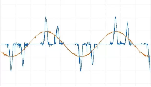
In order to find out the cause of the fault, we used the current clamp meter to measure the current of the equipment, but found that the current values ​​measured by several clamp meters are very different. For example, the field test chart in the following figure shows. Which value is correct? Figure 2 shows the current waveform.
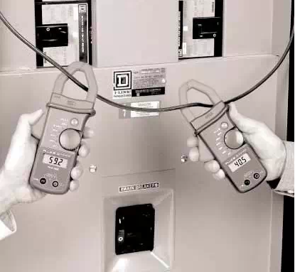
The current on the left in Figure 1 is 5.92A and the current on the right is 4.05A.
What is a valid value (root mean square value)?
The effective value of the alternating current (RMS) is equal to the magnitude of the direct current that produces the same amount of heat in the same resistive load loop. When AC is used, the heat generated by the resistor is proportional to the square of the average current in a cycle. In other words, the amount of heat generated is proportional to the average of the square of the current, that is, the value of the square of the current value squared is also proportional to the effective value. (Since the square is always positive, there is no need to consider the polarity problem)
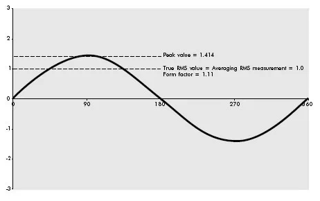
For a pure sine wave as shown in Figure 2, the effective value is 0.707 times the peak value (or the peak value is 1.414 times the effective value). In other words, the peak current of a pure sine wave with an effective value of 1 ampere is 1.414 amps. If the waveform value is simply averaged (inverted against a half negative waveform), the average value is 0.636 times the peak value, or 0.9 times the effective value. Figure 3 shows these two important proportional relationships.
Crest factor = peak/valid value = 1.414
Crest factor = effective value / average value = 1.111
At the same time, the average value is much smaller at 0.55 amps.

At this point, it is not difficult to understand why the circuit breaker will fail and frequently trip by mistake under the condition of “not full loadâ€. Therefore, for signal measurement of non-linear loads, it is necessary to select the “true rms†meter for the measurement in order to correctly evaluate the actual current and thus properly select the appropriate wire.
Zhiyuan Electronics' PA series power analyzers provide accurate true RMS measurements. Figure 5 shows the measurement principle diagram of the power analyzer.
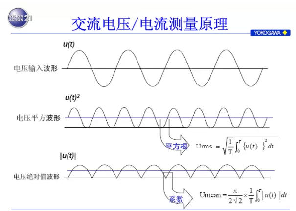
Figure 5 Power Analyzer Measurement Principle With the rapid development of power electronics, switching technology has been widely applied, and the development of silicon carbide technology has enabled higher switching frequencies to be achieved to meet higher-efficiency power supply designs. The PA series power analyzers independently developed by Zhiyuan Electronics have a bandwidth of up to 5MHz and a sampling rate of up to 2MS/s, meeting the need for high-frequency measurement in the future.
In order to find out the cause of the fault, we used the current clamp meter to measure the current of the equipment, but found that the current values ​​measured by several clamp meters are very different. For example, the field test chart in the following figure shows. Which value is correct? Figure 2 shows the current waveform.
The current on the left in Figure 1 is 5.92A and the current on the right is 4.05A.
Figure 2 corresponds to the current waveform
From the current waveform, it can be seen that the load is a non-linear load and the waveform is not a standard sine wave. In Figure 1, the left ammeter is an rms meter and the right is an average meter calibrated by rms. So why are the current values ​​measured by these two ammeters so different? Before you understand the difference between them, you must first understand the exact meaning of the effective value. What is a valid value (root mean square value)?
The effective value of the alternating current (RMS) is equal to the magnitude of the direct current that produces the same amount of heat in the same resistive load loop. When AC is used, the heat generated by the resistor is proportional to the square of the average current in a cycle. In other words, the amount of heat generated is proportional to the average of the square of the current, that is, the value of the square of the current value squared is also proportional to the effective value. (Since the square is always positive, there is no need to consider the polarity problem)
For a pure sine wave as shown in Figure 2, the effective value is 0.707 times the peak value (or the peak value is 1.414 times the effective value). In other words, the peak current of a pure sine wave with an effective value of 1 ampere is 1.414 amps. If the waveform value is simply averaged (inverted against a half negative waveform), the average value is 0.636 times the peak value, or 0.9 times the effective value. Figure 3 shows these two important proportional relationships.
Crest factor = peak/valid value = 1.414
Crest factor = effective value / average value = 1.111
Figure 3 pure sine wave
When measuring a pure sine wave (only for pure sine waves), simply measuring the average value (0.636 times the peak value) and multiplying it by the factor 1.111 (that is, 0.707 times the peak value) is completely correct. Also known as a valid value. This method is widely used for all analog gauges (where the average is achieved by the inertia and damping of the coil motion) and all old-style, instrumentation, and most ammeter digital multimeters. This technique is called the "average reading, calibrated according to the effective value" measurement method. The problem is that this measurement method is only applicable to pure sine waves, and there is no pure sine wave at all in actual electrical devices. The waveform diagram shown in Figure 4 is a typical current waveform generated after connecting to a personal computer. The root mean square value is still 1 ampere, but the peak value is obviously higher than the peak value when pure sine wave, it is 2.6 ampere. At the same time, the average value is much smaller at 0.55 amps.
Figure 4 shows the typical current waveform of a personal computer
If this waveform is measured with an "average reading, calibrated with effective value" meter, it reads 0.61 amps, which is nearly 40% less than the true rms value (1 amp). At this point, it is not difficult to understand why the circuit breaker will fail and frequently trip by mistake under the condition of “not full loadâ€. Therefore, for signal measurement of non-linear loads, it is necessary to select the “true rms†meter for the measurement in order to correctly evaluate the actual current and thus properly select the appropriate wire.
Zhiyuan Electronics' PA series power analyzers provide accurate true RMS measurements. Figure 5 shows the measurement principle diagram of the power analyzer.
Figure 5 Power Analyzer Measurement Principle
1. According to request it can do a single-stage and continuous cutting.
2. Operation of this machine is simple, reduced operational requirements of workers.
3. Machine with high degree automation, can achieve a continuous, intermittent feeding, effectively improve work efficiency;
4. Simple operation, flexible adjustment and stable operation.
5. Multi -purpose machine, can complete continuous feed and cutting length.


Angle Iron Root Cleaning Machine,Angle Bar Root Cleaning Machine,Angle Steel Machine,Heel Milling Machine for Angle Tower
Shandong ShuoFang Environmental Technology Co., Ltd. , https://www.chinafincnc.com